Now includes a FREE upcut bit!!
In stock now, all you need to start projects today!
Maslow Default Frame Assembly One unique thing about the Makermade CNC is that each maker builds their own frame. The folks at Maslow came up with a great frame design in the beginning, and then as. On this page you can find photos and descriptions of all the items shipped in the Maslow CNC Base Machine Kit box and the Maslow CNC Z Axis Kit box. Please note that the Z Axis Kit parts require a separate order of $60 in addition to the $350 Regular Machine Kit. The Maslow CNC was presented at the Maker Faire Bay Area for the world to see in 2017. Their first transaction followed shortly after- a sale of four batches of CNC kit. Soon after the community took off in 2017, packing and shipping the kits to cater to the demands of people from all over the world became taxing for the founders. These wall/frame brackets are the very first of their kind. Use to mount your CNC to the wall, or improve accuracy and rigidity for your stand-alone frame. Benefits over standard Maslow frame setup: faster frame setup, with fewer materials; powder-coated, laser-cut steel provides increased rigidity; reduced frame footprint (more shop space).
In stock with free projects, software, and support all included. Ships same day.
Original Maslow + Metal Sled, Cbeam Z axis, Arduino enclosure & more.
Our complete kit takes off where the orginal left off with many upgraded features and quicker assembly times.
Make your designs come to life with the Maker Made 1/4' CNC Bit.
Set of 2 drive chains
GRBL based motor shield for use with Arduino DUE micro-controller board (not included).
The perfect bit for making signs and detailed cuts like lettering!
A bundle of our most popular bits, this 3-pack of 1 Up cut, 1 Down cut, and 1 Compression router bit provides a great starter set of bits for your most common cutting needs, at a nearly 15% savings versus buying individually. All three bits are solid carbide, with a 0.25in diameter shank and overall length of 2.5in.
Ring and bearing kit that ensures smooth and accurate cuts on your Maslow CNC.
1/4' Spiral Up Cut Bits
1/4' CNC Compression Bit
The complete Z-Axis kit for the Maslow CNC. Automates the cut depth of the router bit.
The latest shield v1.4 offers many improvements over it's predecessor.
This is a kit to build a linkage system for a Maslow CNC machine that enables triangular kinematics (as opposed to quadrilateral kinematics) for more accurate cuts and a more stable router sled.
One Motor/Encoder/Gear Box Unit. These are identical to the motors in the original Maslow kit and are surplus from the last batch of kits sold.
One pair of Sled Ring Bearing Carriages to hold bearings as the roll along sled rings.
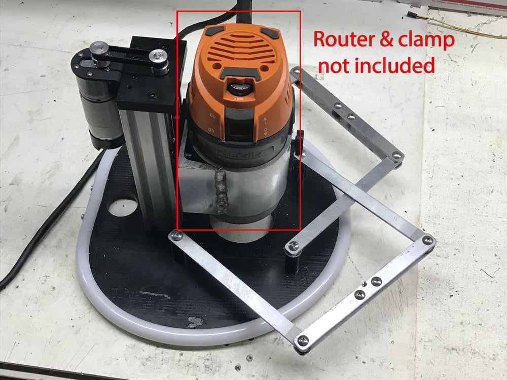
CNC Laser Cut 12 lb base with 7' long arm linkage kit & z axis compatable with most routers
Two 6 ft long bars with coupler and laser cut holes to mount the motors 10' or 12' apart
Surplus hardware bag from Maslow kits
A surplus Maslow hardware bag
Bosch POF 1200 Z-axis kit 2.0
The Maslow Arduino shield version 1.2b
Maker Made Maker300 3D Printer
This L bracket is used to attach the ring to the sled and two of them together are used to hold the z-axis motor.
Maslow Power Supply with US Plug
One set of (4) sled ring bearings.
One Keyestudio MEGA 2560 R3 micro controller (Arduino compatible) with USB cord + extension to connect to your computer.
Maslow power supply with EU plug
Made with higher grade materials than original motors. Direct from manufacturer.
Bar's bolt together Maslow frame design
This frame is designed to use bolts to attach the critical parts together. Using bolts makes the frame easy to take appart and quick to assemble.
The original OnShape CAD file is here: OnShape
This frame is designed to go together in a few hours. It is designed to be very easy and quick to build, but requires that you have a socket set. The required tools for this build are a screw driver, a tape measure, a saw which can cut both 2x4s and plywood, a drill, and either a socket set or a wrench set.
The completed machine will look like this:
Step 1: Buy materials
This design is intended to use imperial hardware, but I am certain that similar materials are available in metric sizes. None of the material sizes or bolt sizes are critical. To build this design you will need:
- 3x 10' 2x4s
- 2x 8' 2x4s
- 2x 4'x8' sheets of 3/4 Plywood (Note, you can get away with one sheet if you don't mind having the sled and a few other parts cut out of the back of the machine)
- 2x bricks
- 2x 3/8' by 10' hex bolts with 1 nut and 2 washers each (available at Lowes, not stocked at Home Depot)
- 2x 1/4' by 5' carriage bolts with 1 nut and 1 washer each
- 4x 1/4' by 3.5' carriage bolts with 1 nut and 1 washer each
img' />img' />
Step 2: Cut the 2x4s
Cut your three 10' 2x4s and two 8' 2x4s as shown in the picture below. None of these cuts are of a critical length. Small errors in the lengths of any of these parts will not affect the accuracy of the machine.
Note that the top 2x4 is a full 10' so no cuts are needed. For the remaining 2x4's some amount will be left over after all cuts. This leftover can be set aside and is not needed. You may want to use your best and straightest board for the top beam (the uncut 10' board)
You should now have 13 cut parts like this:
Step 3: Drill 1/4 inch holes for bolts
Drill holes for the bolts in the parts at the locations shown below. Feel free to use the next size up drill bit to make the bolts go through easier.
Note that all measurements are referenced to the ends of the parts and that these holes can be drilled free hand. They do not need to be perfect or drilled on a drill press.
Step 4: Drill 3/8ths inch holes for bolts
Drill holes for the bolts at the locations shown below. Feel free to use the next size up drill bit to make the bolts go through easier.
Note that the hole through leg part A passes through the beam in the long direction, not the short direction. Drilling straight through the beam in the long direction can be tricky. Consider using one of these techniques or a drill press if you are concerned you may have difficulty.
Your parts should now have holes like this:
img' />img' />
Step 5: Cut plywood spacers
Cut two 3.5 inch plywood squares from one sheet of plywood and drill a 3/8ths inch or larger hole in the center.
Step 6: Bolt together the legs
Assemble the legs using one leg piece each of leg piece A, B, and C, one spacer block with a 1/4 inch hole, on 5' bolt and two 3.5' bolts as shown below.
Repeat this process for the other leg. Note that making them mirror images of each other rather than identical will give the final machine symmetry which could be aesthetically pleasing.
Step 7: Attach the cross beam
Using the two 10' bolts, attach the top beam to the frame with two 2x4 spacers and one 3/4 inch plywood spacer between the beam and the legs. Tighten the bolts well to ensure that there is no play in the connection.
Step 8: Stand it up and attach the backing plywood
Stand up the legs and screw the backer plywood to the legs. Use one screw in each corner, as many screws in the middle are not needed and you may run into them accidentally when routing.

Step 9: Attach the motors
Screw the motor mounting brackets to the ends of the beam flush with the front edge using four of the short wood screws. Screw these down tightly - a lot of torque is applied to these when calibrating the motors later - you don't want them to move.
Attach the motors using the small screws and lock washers.
Step 10: Attach the Arduino and electronics
Attach the Arduino to the back of the plywood using the small screws and standoffs, then reconnect the electronics. Make sure to allow for the length of the cables for the motors. If you would like to reference them, the instructions for connecting the electronics are https://github.com/MaslowCNC/Electronics/wiki/Electronics-Setup.
img' />img' />
Step 11: Install chain hardware
Attach the two sprockets using the included set screw and Allen wrench.
Mark the middle of the top beam and install the two pulleys for the cable system just to either side of the center.
Place a screw in the top beam just to the inside of the motor and on the bottom of the top beam. Hammer in one of the small nails in the hardware bag leaving a little more than 1/4 inch protruding. The chain will attach to this nail. (If the chain won't fit over the nail, you might want to delay putting in the nails until the next step).
Step 12: Hook up the chain
Take the chain and loop it over the sprocket leaving the outside end dangling. Hook the inside end of the chain on the small nail. Take the stretchy cord and form a loop in each end using zip ties. Hook one end over the screw to the inside of the motor. Place the idler sprocket and S hook in the loop of the chain, then hook the other end of the streachy cord to the S hook.

Maslow Cnc Metal Frame
img' />img' />img' />img' />
Now that we have completed building the frame, we need to use it to cut the sled. Instructions to build a temporary sled and use it to cut the final version can be found here.
Notes to improve the design:
It would be much easier to put this together if all the holes were equally distant from each end of the board so that the parts were reversible.
This design is intended to use imperial hardware, but I am certain that similar materials are available in metric sizes. None of the material sizes or bolt sizes are critical. To build this design you will need:
3x 10' 2x4s
2x 8' 2x4s
2x 4'x8' sheets of 3/4 Plywood (Note, you can get away with one sheet if you don't mind having the sled and a few other parts cut out of the back of the machine)
2x bricks
2x 3/8' by 10' hex bolts with 1 nut and 2 washers each (available at Lowes, not stocked at Home Depot)
2x 1/4' by 5' carriage bolts with 1 nut and 1 washer each
4x 1/4' by 3.5' carriage bolts with 1 nut and 1 washer each
Maslow Cnc Setup
img' />img' />
